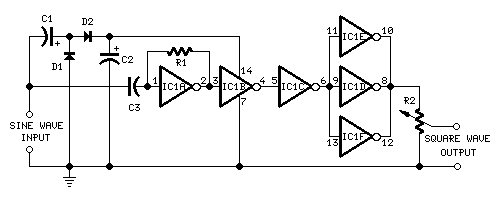
Self-powered Sine to Square wave Converter Circuit
Converts sine to square waves without a power-source
Useful as a test instrument for audio purposes
Parts:
R1 1M 1/4W Resistor
R2 100K Linear Potentiometer
C1,C2 100�F 25V Electrolytic Capacitors
C3 10nF 63V Polyester Capacitor
D1,D2 1N4148 75V 150mA Diodes
IC1 4069 Hex Inverter IC
Device purpose:
This circuit is intended to provide good square waves converting a sine wave picked-up from an existing generator. Its major feature consists in the fact that no power-source is needed: thus it can be simply connected between a sine wave generator and the device under test.
The input sine wave feeds a voltage doubler formed by C1, C2, D1 & D2 that powers the IC. IC1A amplifies the input sine wave, other inverters included in IC1 squaring the signal and delivering an output square wave of equal mark/space ratio and good rise and fall times through the entire 20Hz-20KHz range.
Notes:
Best performances are obtained with an input sine wave amplitude from 1V RMS onwards.
Output square wave amplitude is proportional to input amplitude.
Minimum sine wave input amplitude needed for good performance: 750mV RMS.
Output square wave amplitude with 1V RMS input: 3V peak to peak, with R2 set at max.
Minimum output square wave amplitude: 2V peak to peak, with R2 set at max.
Substituting the two silicon diodes with germanium types (e.g. AA118, AA119), the minimum input threshold can be lowered.
This circuit won �50 and was published on ELECTRONICS WORLD "Circuit Ideas", February 2000 issue, page 135.
author:RED Free Circuit Designs,
website: http://www.redcircuits.com/

