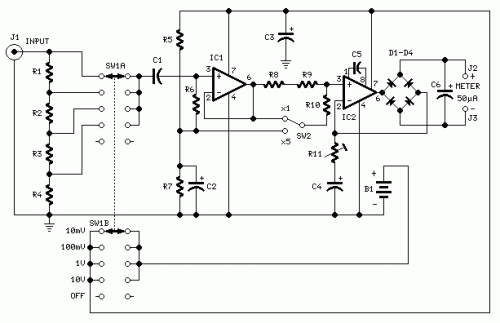
Precision Audio Millivoltmeter Circuit
Measures 10mV to 50Volt RMS in eight ranges
Simply connect to your Avo-meter set @ 50uA range
Parts:
R1 909K 1/2Watt 1% Metal Oxide Resistor
R2 90K9 1/2Watt 1% Metal Oxide Resistor
R3 9K09 1/2Watt 1% Metal Oxide Resistor
R4 1K01 1/2Watt 1% Metal Oxide Resistor
R5 100K 1/4W Resistor
R6 2M2 1/4W Resistor
R7 82K 1/4W Resistor
R8 12K 1/4W Resistor
R9 1K2 1/4W Resistor
R10 3K3 1/4W Resistor
R11 200R 1/2W Trimmer Cermet
C1 330nF 63V Polyester Capacitor
C2,C3 100uF 25V Electrolytic Capacitor
C4 220uF 25V Electrolytic Capacitor
C5 33pF 63V Polystyrene Capacitor
C6 2u2 63V Electrolytic Capacitor
D1-D4 1N4148 75V 150mA Diodes
IC1 CA3140 Op-amp
IC2 CA3130 Op-amp
SW1 2 poles 5 ways rotary switch
SW2 SPDT switch
J1 RCA audio input socket
J2,J3 4mm. output sockets
B1 9V PP3 Battery
Clip for PP3 Battery
Notes:
Connect J2 and J3 to an Avo-meter set @ 50uA range
Switching SW2 the four input ranges can be multiplied by 5
Total fsd ranges are: 10mV, 50mV, 100mV, 500mV, 1V, 5V, 10V, 50V
Set R11 to read 1V in the 1V range, with a sinewave input of 1V @ 1KHz
Compare the reading with that of another known precision Millivoltmeter or with an The oscilloscope reading must be a sinewave of 2.828V peak to peak amplitude
Frequency response is flat in the 20Hz-20KHz range
If you have difficulties in finding resistor values for R1, R2, R3 & R4, you can use the following trick:
R1 = 10M + 1M in parallel
R2 = 1M + 100K in parallel
R3 = 100K + 10K in parallel
R4 = 1K2 + 6K8 in parallel
All resistors 1% tolerance
author:RED Free Circuit Designs,
website: http://www.redcircuits.com/

