LM317 Regulator Circuit
Description:
I constructed this voltage regulator to power my two way mobile radio from the car cigarette lighter circuit. It has many other uses and the voltage can easily be adjusted by the use of a potentiometer. The voltage regulator is an LM317T, and should accept up to about 14 volts without problems. It can handle up to 1 amp, but you WILL need a heatsink on the voltage regulator.
The components are:
R1: 270R
R2: 2K Cermet or carbon preset potentiometer
C1: 100nF
C2: 1uF tantalum
LM317T Voltage regulator
Heatsink
PCB board
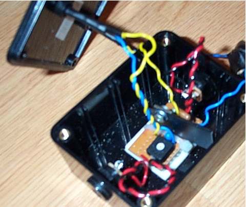
I also added DC power jacks for input and output on my voltage regulator, a green power LED, and a red over-voltage LED. The over voltage LED uses a zener diode to switch on the LED at a certain preset voltage, this can be varied depending on the voltage of the zener diode, I used a 6.2v zener diode. If you plan to vary the voltage for the different items you power, don't bother adding this feature. If you only plan to use items that run on one voltage, this is a very useful feature and will save plugging in and damaging your valuable (or not so valuable) equipment. You can even add a relay to switch off the power if the over voltage LED turns on, but bear in mind it will have to work from the voltage of the zener diode right up to the input voltage. I couldn't add a relay because I couldn't find any that operated from 6.2-13.8 volts. Anyway, the schematic is shown above, the over voltage and power LED are not included in them because it is assumed that anybody who makes this will understand how to use a zener diode:
This is what the final product should look like inside:
This is an outside view of the finished voltage regulator:

Here is what my voltage regulator is intended to power: 