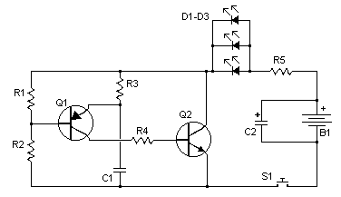
IR Remote Control Jammer Circuit
Don't like your little brother's TV channel selection? Hate the volume your wife sets the stereo at? Want to just annoy someone? This circuit does all that and more by jamming most IR remote signals. The circuit releases a flood of pulsing IR light that confuses the reciever by corrupting the data stream.
Parts:
R1 100K 1/4W Resistor
R2 150K 1/4W Resistor
R3 10K 1/4W Resistor
R4 1K 1/4W Resistor
R5 See "Notes"
C1 10nF Ceramic Disc Capacitor
C2 1uF Electrolytic Capacitor
D1, D2, D3 High Output IR LED
Q1 2N4403 PNP Transistor
Q2 2N4401 NPN Transistor
S1 Normally Open Momentary Push Botton
B1 4.5V Battery (Three "AA"'s In Series)
MISC Wire, Case, Board
Notes:
1. Email Carl with questions, comments, etc.
2. You may need to adjust the value of R3 for the right frequency. A pot can be used.
3. You may only need one IR LED.
4. It goes without saying that this circuit should be used with descretion.
author:Carl, [email protected]
website: http://www.aaroncake.net

