Infa-Red Remote Control Circuit
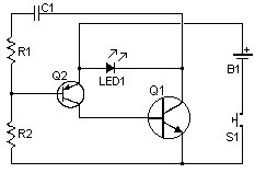
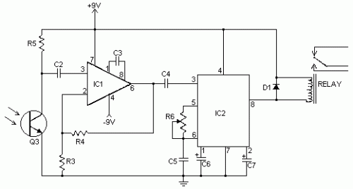
I have received a number of emails requesting schematics for infa-red remotes. So here is one. This remote transmits a tone using an infa-red LED. This tone is decoded by the receiver. Since the receiver only switches when it "hears" the tone, there are no accidental activations.
Circuit diagram For Transmitter

Parts:
R1 22K 1/4W Resistor
R2 1 Meg 1/4W Resistor
R3 1K 1/4W Resistor
R4, R5 100K 1/4W Resistor
R6 50K Pot
C1, C2 0.01uF 16V Ceramic Disk Capacitor
C3 100pF 16V Ceramic Disk Capacitor
C4 0.047uF 16V Ceramic Disk Capacitor
C5 0.1uF 16V Ceramic Disk Capacitor
C6 3.3uF 16V Electrolytic Capacitor
C7 1.5uF 16V Electrolytic Capacitor
Q1 2N2222 NPN Silicon Transistor or 2N3904
Q2 2N2907 PNP Silicon Transistor
Q3 NPN Phototransistor
D1 1N914 Silicon Diode
IC1 LM308 Op Amp IC
IC2 LM567 Tone Decoder
LED1 Infa-Red LED
RELAY 6 Volt Relay
S1 SPST Push Button Switch
B1 3 Volt Battery or Two 1.5V batteries in series
MISC Board, Sockets For ICs, Knob For R6, Battery Holder
RELAY 6 Volt Relay
Notes:
1. To adjust the circuit, hold down S1 while pointing LED1 at the receiver. Adjust R6 until you hear the relay click.
2. You can increase range by using a high output LED for LED1.
3. Bright light will stop the receiver from responding to the transmitter.
Author:
website: http://www.aaroncake.net

