Electronic Keypad
Description:
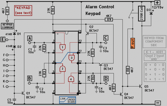
The IC is a quad 2 input "AND" gate, a CMOS 4081. These gates only produce a HIGH output, when BOTH the inputs are HIGH. When the key wired to 'E' is pressed, current through R1 and D1 switchs Q5 on.The relay energises; and Q5 is 'latched on' by R8. Thus, the Alarm is set by pressing a single key,say one of the two non-numeric symbols.
The alarm will switch off when the 4 keys connected to "A,B,C,D" are pushed in the right order.The circuit works because each gate 'Stands' upon its predecessor.If any key other than the correct key is pushed, then gate 1 is knocked out of the stack, and the code entry fails. Pin 1 is held high by R4. This 'Enables' gate 1; and when button 'A' is pressed, the output at pin 3 will go high. This output does two jobs.It locks itself 'ON' through R2 and it 'Enables' gate 2, by taking pin 5, high. Now, if 'B' is pressed, the output of gate 2, at pin 4 will go high. This output does two jobs. It locks itself 'ON' through R3 and it 'Enables' gate 3 by taking pin 12 high.
Now, if 'C' is pressed, the output of gate 3 will lock itself 'ON' through R5 and, by taking pin 8 high, 'Enable' gate 4. Pressing 'D' causes gate 4 to do the same thing; only this time its output, at pin 10, turns Q4 'ON'. This takes the base of Q5 to ground, switching it off and letting the relay drop out. This switches the alarm off.
Any keys not connected to 'A B C D E' are wired to the base of Q1. Whenever 'E' or one of these other keys is pressed, pin 1 is taken low and the circuit is reset. In addition, if 'C' or 'D' is pressed out of sequence, then Q2 or Q3 will take pin 1 low and the circuit will reset. Thus nothing happens until 'A' is pressed.Then if any key other than 'B' is pressed, the circuit will reset.
Similarly, after 'B', if any key other than 'C' is pressed,the circuit will reset. The same reasoning also applies to 'D'.
The Keypad needs to be the kind with a common terminal and a separate connection to each key. On a 12 key pad, look for 13 terminals. The matrix type with 7 terminals will NOT do. Wire the common to R1 and your chosen code to 'A B C D'. Wire 'E' to the key you want to use to switch the alarm on. All the rest go to the base of Q1.
The diagram should give you a rough guide to the layout of the components, if you are using a stripboard. The code you choose can include the non-numeric symbols.In fact, you do not have to use a numeric keypad at all,or you could make your own keypad.
I haven't calculated the number of combinations of codes available, but it should be in excess of 10 000 with a 12 key pad; and, after all, any potential intruder will be ignorant of the circuit's limitations. Of Course, if you must have a more secure code, I can think of no reason why you shouldn't add another 4081 and continue the process of enabling subsequent gates. Or you could simply use a bigger keypad with more "WRONG" keys.
Any small audio transistors should do. The 27k resistors could be replaced with values up to 100k. And the only requirements for the 4k7 resistors is that they protect the junctions while providing enough current to turn the transistors fully on.
Capacitors (C1 C2 C3 C4 C5) are there to slow response time and overcome any contact bounce. They are probably unnecessary.

