Low-distortion Audio-range Oscillator Circuit
Generates very low-distortion sine waves up to 1V RMS
No thermistors required - No settling time
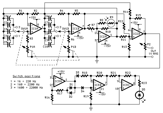
Circuit diagram
Parts:
P1 10K Log. Potentiometer (Dual-ganged)
P2 2K2 Linear Potentiometer
R1,R2,R4,R5 3K3 1/4W Resistors
R3,R6 820R 1/4W Resistors
R7 10K 1/2W Trimmer Cermet
R8 22K 1/4W Resistor
R9 Photo resistor (any type)
R10 8K2 1/4W Resistor
R11,R12,R14,R15 3K3 1/4W Resistors
R13 2K7 1/4W Resistor
R16--R20 3K3 1/4W Resistors
R21 56K 1/4W Resistor
R22 68K 1/4W Resistor
R23 1K 1/4W Resistor
C1,C6 220pF 63V Polystyrene Capacitors
C2,C7 8n2 63V Polyester Capacitors
C3,C8 82nF 63V Polyester Capacitors
C4,C9 150nF 63V Polyester Capacitors
C5,C10 680nF 63V Polyester Capacitors
D1--D4 1N4148 75V 150mA Diodes
D5 LED 5mm. Red
IC1,IC2 NE5532 Low noise Dual Op-amps
IC3 TL084 Quad BIFET Op-Amp
SW1 2 poles 3 ways rotary switch
Comments:
Producing low-distortion sine waves, this oscillator operates over the range 16 to 22000 Hz. The circuit is based on two articles that have appeared earlier in Wireless World - Roger Rosens' "Phase -Shifting Oscillator", February 1982 pp. 38-41, and J. L. Linsley Hood's "Wien-Bridge Oscillator with low harmonic distortion" from May 1981 pp. 51-53.
This design features the simplicity of the Rosens' circuit but avoids the use of a thermistor. Instead, oscillator stability is controlled by means of a common photo-resistor driven by a LED, as suggested in the Linsley Hood article.
There is no settling time when the oscillator's frequency is changed and no bouncing of the output waveform. Use of an expensive and sometimes difficult to obtain thermistor is avoided.
Technical data:
Output voltage:
Sine wave, 1V RMS max.
Total harmonic distortion @ 1V RMS output:
Frequency Reading
100Hz = 0.0035%
300Hz = 0.0028%
1kHz = 0.002 %
3kHz = 0.002 %
10kHz = 0.001 %
Notes:
Any common photo-resistor and 5mm. red LED can be used, provided they are in close contact and enclosed in a light-proof small box. I used the metal screen of a small IF transformer for AM transistor radios sealed with black insulating tape.
The 10K trimmer must be set to obtain a 1V RMS output.
The circuit must be supplied by a + and - 15V dual regulated supply. Common 7815 and 7915 regulator ICs should be used for this purpose.
This circuit was awarded with publication in ELECTRONICS WORLD "Circuit Ideas", February 2003 issue, page 38.
author:RED Free Circuit Designs,
website: http://www.redcircuits.com/