Electromagnetic Field Probe with Meter Output Circuit
Circuit diagram
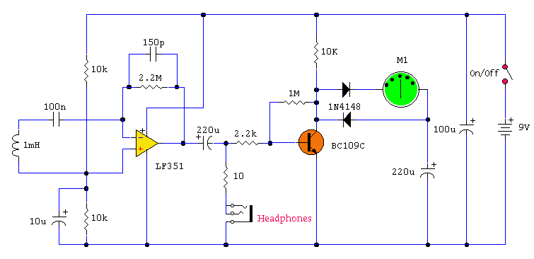
Notes:
This tester is designed to locate stray electromagnetic (EM) fields. It will easily detect both audio and RF signals up to frequencies of around 100kHz. Note, however that this circuit is NOT a metal detector, but will detect metal wiring if it conducting ac current. Frequency response is from 50Hz to about 100kHz gain being rolled off by the 150p capacitor, the gain of the op-amp and input capacitance of the probe cable. Stereo headphones may be used to monitor audio frequencies at the socket, SK1.
Probe Construction:
I used a radial type inductor with 50cm of screened cable threaded through a pen tube. The cable may be used with a plug and socket if desired. My probe is shown below:
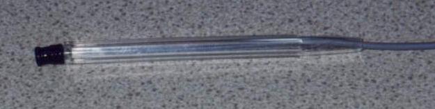
A layer of insulating tape or glue is used to secure the pen body to the inductor.
Meter Circuit:
The output signal from the op-amp is an ac voltage at the frequency of the electro-magnetic field. This voltage is further amplified by the BC109C transistor, before being full wave rectified and fed to the meter circuit. The meter is a small dc panel meter with a FSD of 250uA. Rectification takes place via the diodes, meter and capacitor.
Testing:
If you have access to an audio signal generator you can apply an audio signal to the windings of a small transformer. This will set up an electromagnetic field which will be easily detected by the probe. Without a signal generator, just place the probe near a power supply, mains wiring or other electrical device. There will be a deflection on the meter and sound in the headphones if the frequency is below 15KHz.
In Use:
Switch on, plug in headphones (optional) and move the probe around. Any electrical equipment should produce a hum and indicate on the meter.I remember once building a high gain preamp (for audio use). I made a power supply in the same enclosure. The preamp worked, but suffered from an awful mains hum. This was not directly from ripple on the power supply as it was regulated and well smoothed.What I had done was built the audio circuit on a small piece of veroboard, and placed it within a distance that was less than the diameter of the transformer. The transformers own electromagnetic field was responsible for the induced noise and hum. I should however note, that this was when I was new to electronics with very little practical experience. You can now buy toroidal transformers which have a much reduced hum field.
Author:
website: http://www.zen22142.zen.co.uk