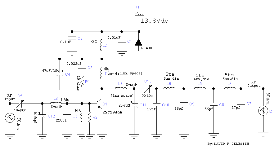
2SC1946A 30 Watt VHF Amplifier
Description:
The 30 watt amplifier schematic shown below provides an appropriate power boost with an input of 4 watt up to 6 watts. The circuit is designed to cover 88-108MHz FM Broadcast Band. However, the circuit is very stable at my place and provides a clean-output through seven (7) element Butter-worth low-pass filter.
Notes:
The heart of the circuit is 2SC1946A VHF RF power transistor. The transistor is specifically designed for operation in frequencies up to 175 MHz, with very good results.
As you can see, the power line is well decoupled. The amplifier current can be over 5 amps. All the coils are made from 16gauge laminated wire (or Silver copper wire can do best) and the RFC can be of HF toroid core (as shown in the picture) or 6 holes ferrite bead.C3 and R1 forms snubber circuit while R2 and C6 prevent the amplifier from self-oscillation at VHF, sometimes you need to add 180 ohms in parallel with L7.That will cause the amplifier to dissipate UNDESIRABLE VHF thereby reducing spurious level.
The photo below is 60Watts VHF power amplifier using the above circuit. Two of 2SC1946A transistors are arranged at 90 degrees to each other and their outputs are combined using "Power Combiner Network'. It is quite difficult to combine powers at VHF and UHF bands.
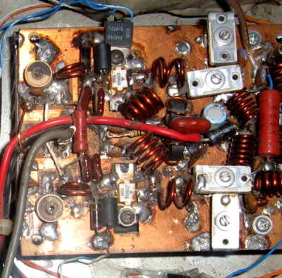
However, I recommend that hobbies should stick to single power design due to its complicity and large rate of INTERFERENCE. (in attempt to go for double transistors which involves power combiner network). Since the two amplifiers are operating in different phase (out of phase).
Tuning:
Tuning of the amplifier is not hard at all. You just have to connect the output to a good antenna with a transmission line (RG214) of 50 ohms. First match the output network, and then do the same to the input network for a maximum power output. By way of adjustment, you can increase the output at its operating frequency.